Two of the most commonly used astigmatism chart are the Clock dial chart and the astigmatism fan chart. This test well controls accommodation as fogging is done prior and has an advantage over the Jackson cross cylinder where one of the focal lines is behind the retina which can disrupt the rest of the accommodation. Due to test complexity for both practitioner and patient, it is less often used in clinical practice compared to the Jackson cross cylinder. But becomes one of the essential test when the Jackson cross cylinder fails.
Optics behind astigmatism clock dial or fan chart:
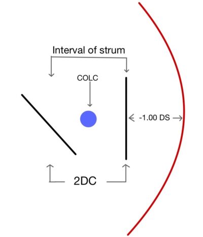
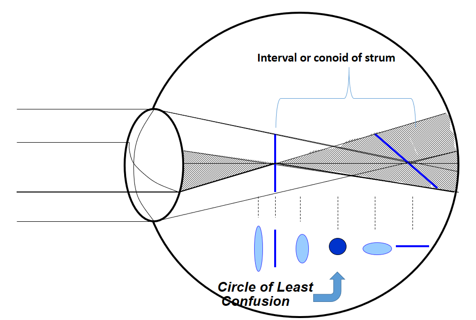
When light rays passed through an optical system which does not have similar curvature in two principal meridians, it causes rays to focus on two focal points rather than making a single focal point. Similarly, when light passes through an astigmatic eye it causes the formation of two focal points. The distance between two focal points is known as the interval or conoid of the strum. The best image in this type of optical system is somewhere in the middle of the interval of strum where there is an equal amount of convergence from one meridian and an equal amount of divergence from another meridian, known as the circle of least confusion. Which gives a compromised but best possible image produced by this system.
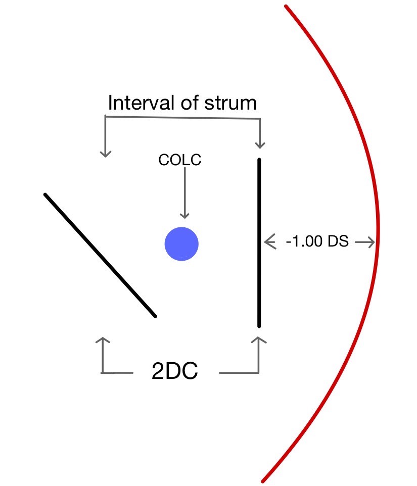
The first step is to place the circle of least confusion on the retina which is done by placing the best vision sphere (BVS) in the trial frame which provides maximum visual acuity (remember to do fogging for hypermetropia patients.
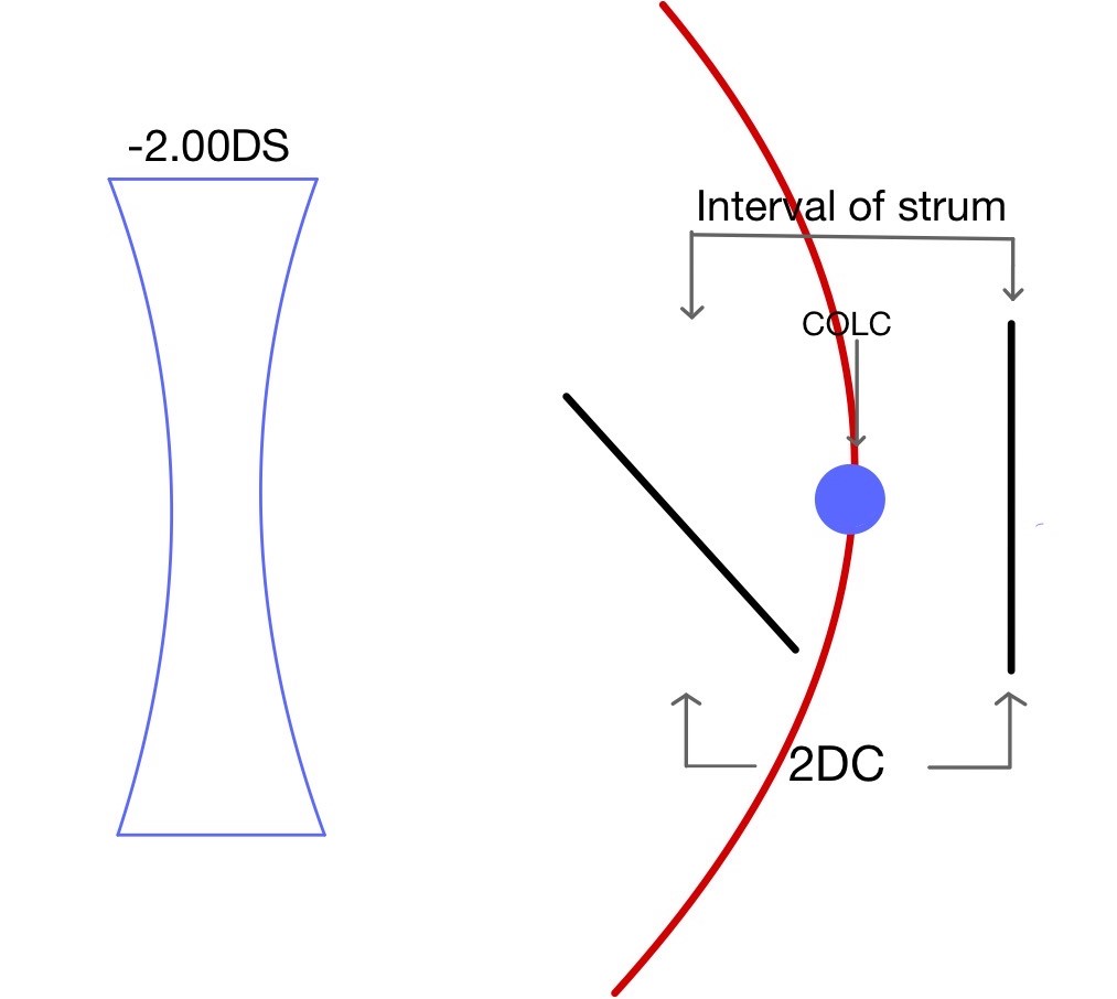
Once the circle of least confusion is on the retina patient visual acuity is recorded. Recording visual acuity will help us to estimate the patient astigmatism amount.
| Vision with COLC on retina | Astigmatism (D) |
| 6/6 | Less than 1 |
| 6/9 | 1.00 |
| 6/12 | 1.50 |
| 6/18 | 2.00 |
| 6/24 | 3.00 |
| 6/36 | 4.00 |
| 6/60 | High |
Based on above mentioned Table 1 plus sphere power is added which will be equal to half of the estimated astigmatism according to patient visual acuity when the Circle of least confusion is on retina. It will bring the line which was behind the retina to the retina, as a result, the patient will see one of the lines on the chart more clearly compare to the other lines.
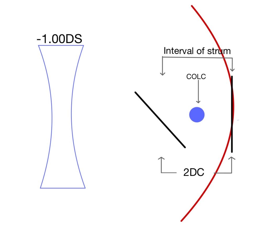
An alternative method is to fog the eye using high spherical plus power and making all line blur so that both lines are in front of the retina and accommodation is at rest. Slowly add minus lens till the patient notice one of the lines is comparatively clear compared to other lines.
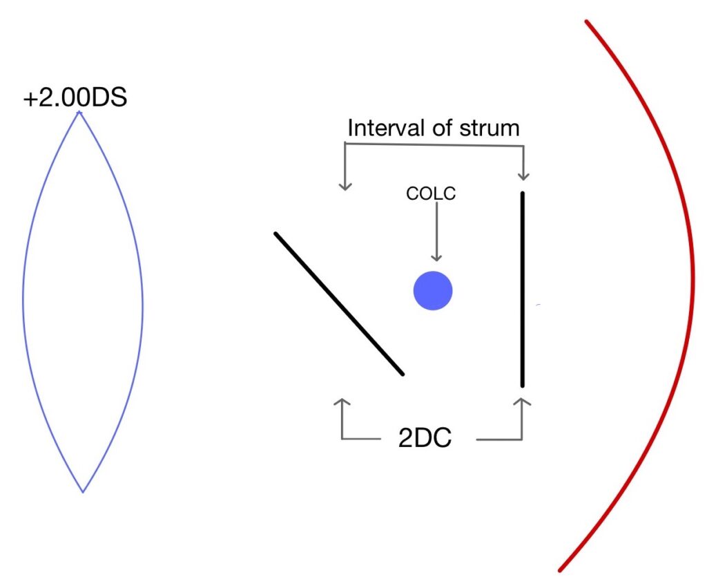
Then examiner begins adding a minus cylinder power lens in 0.25 DC steps and questioning the patient each time sharpness of the lines. Adding minus 0.25 DC brings the line which was in front of the retina starts diverging and will move towards the retina. The examiner continues to add minus 0.25 DC until the patient reports all lines are equally clear.
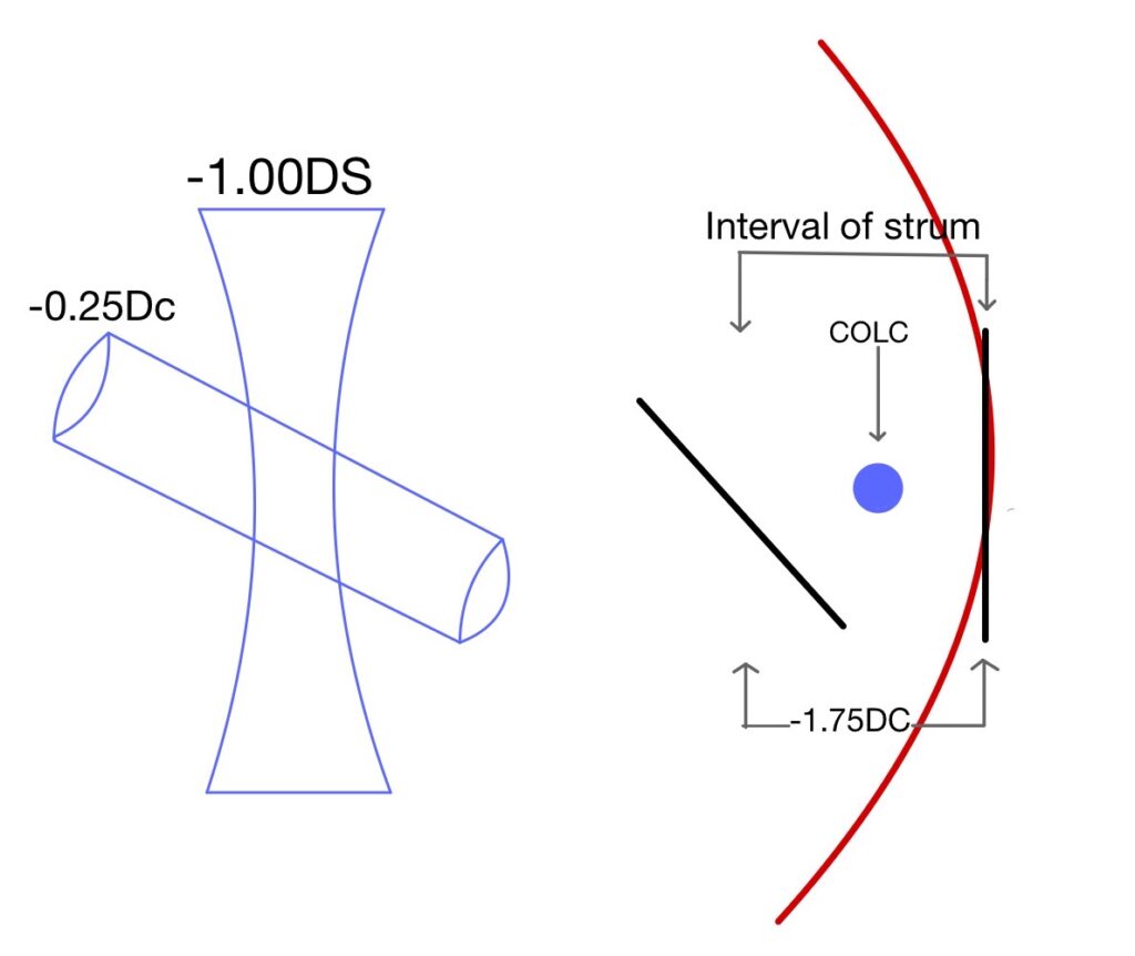
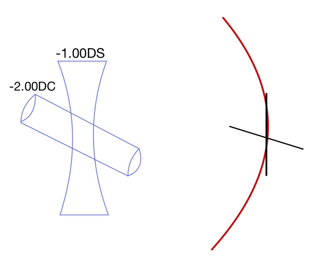
At this point, the examiner add an extra cylinder so that one set of lines become clear which will be 90 degrees apart from a set of the line which was clear earlier. If this happens it means the astigmatism error which we found is correct and an additional 0.25DC is removed from the trial frame.
Click below to learn about the procedure of each test.
Lecturer (Nethradhama School of Optometry)
Moptom

